
嵌入式Linux驱动开发——IIC设备驱动程序
IIC设备驱动程序
IIC设备是一种通过IIC总线直接连接的设备,由于其简单性,被广泛引用于电子系统中。在现代电子系统中,有很多的IIC设备需要进行相互之间的通信。为了提高硬件的效率和简化电路的设计,PHILIPS公司开发了IIC总线。IIC总线可以用于设备间的数据通信。
IIC设备的总线及其协议
IIC总线是由PHILIPS公司开发的两线式串行总线,用于连接微处理器和外部IIC设备。IIC设备产生于20世纪80年代,最初专用于音频和视频设备,现在在各种电子设备中都有广泛的应用。
IIC总线的特点
IIC总线有两条总线线路:一条是串行数据线(SDA),一条是串行时钟线(SCL)。SDA负责数据传输,SCL负责数据传输的时钟同步。IIC设备通过这两条总线连接到处理器的IIC总线控制器上。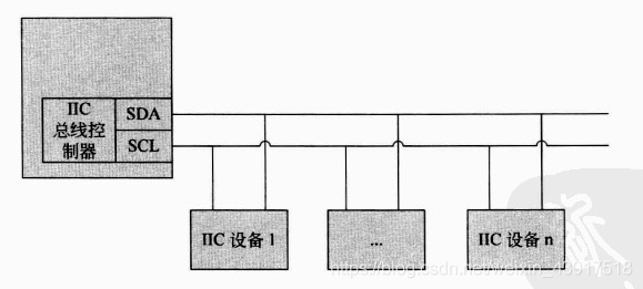
与其他总线相比,IIC总线有许多重要的特点。在选择一种设备来完成特定功能时,这些特点是选择IIC设备的重要依据。下面对IIC设备的主要特点进行简要的总结。
特点:
(1)每个连接到总线的设备都可以通过唯一的设备地址单独访问;
(2)串行的8位双向数据传输,位速率在标志模式下可以达到100kb/s,快速模式下可以达到400kb/s,告诉模式下可达3.4Mb/s;
(3)总线长度最长7.6米左右;
(4)片上滤波器可增加抗干扰能力,保证数据传输;
(5)连接到一条IIC总线上的设备数量只受最大电容400pF的限制;
(6)它是一个多主机系统,在一条总线上可以有多个主机同时存在,通过冲突检测方式和延时等待保护数据不被破坏。同一时间只能有一个主机占用总线。
IIC总线的信号类型
IIC总线在传输数据的过程中有3种类型的信号:开始信号、结束信号和应答信号。这些信号由SDA线和SCL线的电平高低变化来表示。
开始信号(S):当SCL为高电平时,SDA由高电平向低电平跳变,表示将要开始传输数据;
结束信号(P):当SCL为高电平时,SDA由低电平向高电平跳变,表示结束传输数据;
相应信号(ACK):从机主接收到8位数据后,在第9个时钟周期,拉低SDA电平,表示已经收到信号,这个信号称为应答信号。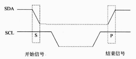
IIC总线的数据传输
在分析IIC总线的数据传输前需要知道主机和从机的概念:
1.主机和从机
IIC总线中发送命令的设备称为主机,对于ARM处理器来说,主机就是IIC控制器。接受命令并响应命令的设备称为从机。
2.主机向从机发送数据
主机通过数据线SDA向从机发送数据。当总线空闲时,SDA和SCL信号都处于高电平。
IIC设备的硬件原理
S3C2440处理器中集成了一个IIC控制器,用来管理IIC设备,实现设备的数据接收和发送功能。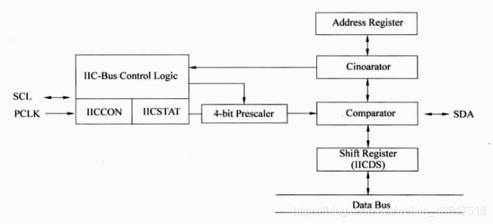
IIC设备驱动程序的层次结构
因为IIC设备种类丰富,如果为每一个IIC设备写一个驱动程序,那么Linux内核中关于IIC设备的驱动就将非常庞大。这不设计方式不符合软件工程中的代码复用规则,所以需要对IIC设备驱动中的代码进行层次化组织。
这里简单的将IIC设备驱动的层次分为:设备层,总线层。理解这两个层次的重点是理解4个数据结构,这4个数据结构是:i2c_driver、i2c_client、i2c_algorithm、i2c_adapter。i2c_driver、2c_client属于设备层;i2c_algorithm、i2c_adapter属于总线层。
IIC设备层
IIC设备层由IIC设备和对应的设备驱动程序组成,分别用数据结构i2c_client和i2c_driver表示。
结构体i2c_driver和i2c_client的关系较为简单,其中i2c_driver表示一个IIC设备驱动程序,i2c_client表示一个IIC设备。这两个结构体之间通过指针连接起来,其关系如图所示: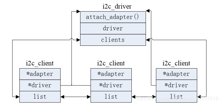
IIC总线层
IIC总线层由总线适配器和适配器驱动程序组成,分别用数据结构i2c_adaptert和i2c_algorithm表示。
IIC设备层和总线层的关系
大体上,IIC设备驱动程序可以分为设备层和总线层。设备层包括一个重要的数据结构i2c_client。总线层包括两个重要的数据结构,分别是i2c_adapter和i2c_algorithm。一个结构表示一个物理的IIC设备;一个i2c_adapter结构对应一个物理上的适配器;一个i2c_algorithm结构表示适配器对应的传输数据的方法。这三个数据结构的关系如图所示: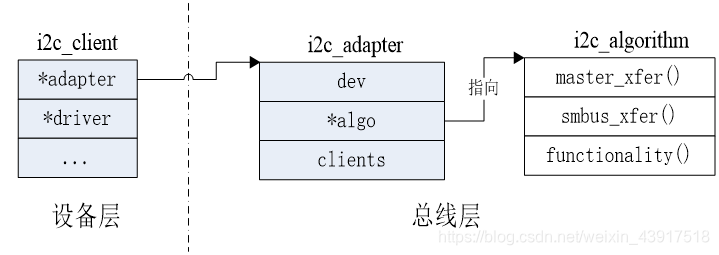
写IIC设备驱动的步骤
IIC设备层次结构较为简单,但是写IIC设备驱动程序却相当的复杂。当工程师拿到一个新的电路板时,面对复杂的Linux IIC子系统,应该如下下手编程呢?首先需要思考的是哪些工作需要自己完成,哪些工作内核已经提供了。这个问题的答案如图所示: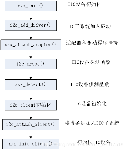
IIC子系统的初始化
在启动系统时,需要对IIC子系统进行初始化。这些初始化函数包含在i2c-core.c文件中。该文件中包含IIC子系统中的公用代码,驱动开发人员只需要用它,而不需要修改它。下面对这些公用代码的主要部门进行介绍。
1.IIC子系统初始化函数i2c_init()
IIC子系统是作为模块加载到系统中的。在系统启动中的模块加载阶段,会调用i2c_init()函数初始化IIC子系统。
static int __init i2c_init(void)
{
	int retval;  //返回值,成功返回0,错误返回负值

	retval = bus_register(&i2c_bus_type);  //注册一条IIC的BUS总线
	if (retval)
		return retval;
	retval = class_register(&i2c_adapter_class);  //注册适配器类,用于实现sys文件系统的部分功能
	if (retval)
		goto bus_err;
	retval = i2c_add_driver(&dummy_driver);  //将一个空驱动注册到IIC总线中
	if (retval)
		goto class_err;
	return 0;

class_err:
	class_unregister(&i2c_adapter_class);  //类注销
bus_err:
	bus_unregister(&i2c_bus_type);  //总线注销
	return retval;
}
2.IC子系统退出函数i2c_exit ()
与i2c_init()函数对应的退出函数是i2c_exit()。该函数完成i2c_init()函数相反的功能。
static void __exit i2c_exit(void)
{
	i2c_del_driver(&dummy_driver);
	class_unregister(&i2c_adapter_class);
	bus_unregister(&i2c_bus_type);
}
适配器驱动程序
适配器驱动程序是IIC设备驱动程序需要实现的主要驱动程序,这个驱动程序需要根据具体的适配器硬件来编写,本节将对失陪器驱动程序进行详细的讲解。
1.s3c2440对应的适配器结构体
i2c_adapter结构体为描述各种IIC适配器提供了通用“模板”,它定义了注册总线上所有设备的clients链表、指向具体IIC适配器的总线通信方法i2c_algorithm的algo指针、实现i2c总线操作原子性的lock信号量。但i2c_adapter结构体只是所有适配器的共有属性,并不能代表所有的类型的适配器。
struct s3c24xx_i2c {
	spinlock_t		lock;
	wait_queue_head_t	wait;
	unsigned int		suspended:1;  //表示设备是否挂起,只用以为确定

	struct i2c_msg		*msg;
	unsigned int		msg_num;
	unsigned int		msg_idx;
	unsigned int		msg_ptr;

	unsigned int		tx_setup;
	unsigned int		irq;  //适配器申请的中断号

	enum s3c24xx_i2c_state	state;
	unsigned long		clkrate;

	void __iomem		*regs;
	struct clk		*clk;  //对应的时钟
	struct device		*dev;  //适配器对应的设备结构体
	struct resource		*ioarea;  //适配器的资源
	struct i2c_adapter	adap;  //适配器的主体结构体

#ifdef CONFIG_CPU_FREQ
	struct notifier_block	freq_transition;
#endif
};
2.IIC适配器加载函数i2c_add_adapter()
当驱动开发人员拿到一块新的电路板,并研究了响应的IIC适配器之后,就应该使用内核提供的框架函数向IIC子系统中添加一个新的适配器。这个过程如下所示:
(1)分配一个IIC适配器,并初始化相应的变量。
(2)使用i2c_add_adapter()函数向IIC子系统添加适配器结构体i2c_adapter。这个结构体已经在第一步初始化了。i2c_add_adapter()函数的代码如下所示:
int i2c_add_adapter(struct i2c_adapter *adapter)
{
	int	id, res = 0;

retry:
	if (idr_pre_get(&i2c_adapter_idr, GFP_KERNEL) == 0)
		return -ENOMEM;  //内存分配失败

	mutex_lock(&core_lock);  //锁定内核锁
	/* "above" here means "above or equal to", sigh */
	res = idr_get_new_above(&i2c_adapter_idr, adapter,
				__i2c_first_dynamic_bus_num, &id);
	mutex_unlock(&core_lock);  //释放内核锁

	if (res < 0) {
		if (res == -EAGAIN)
			goto retry;  //分配没有成功,重试
		return res;
	}

	adapter->nr = id;
	return i2c_register_adapter(adapter);  //注册适配器设备
}
3.IDR机制
IDR机制在Linux内核中指的就是整数ID管理机制。从实质上来讲,这就是一种将一个整数ID号和一个指针关联在一起的机制。这个机制最早是在2003年2月加入内核的,当时是作为POSIX定时器的一个补丁。现在,在内核的很多地方都可以找到IDR的身影。
4.适配器卸载函数i2c_del_adapter()
与适配器加载函数i2c_add_adapter()对应的卸载函数是i2c_del_adapter()。该函数完成与加载函数相反的功能。i2c_del_adapter()函数用于注销适配器的数据结构、删除其总线上所有设备的i2c_client数据结构和对应的i2c_driver驱动程序。并减少其代表总线上所有设备的相应驱动程序数据结构的引用计数(如果到达0,则卸载设备驱动程序)。该函数原型如下:
int i2c_del_adapter(struct i2c_adapter *adap);
5.IIC总线通信方法s3c24xx_i2c_algorithm结构体
s3c24xx_i2c适配器的成员变量adap中的algo成员指向了该适配器的通讯方法s3c24xx_i2c_algorithm结构体。
6.适配器的传输函数s3c24xx_i2c_doxfer()
s3c24xx_i2c_doxfer()函数操作适配器来完成具体的数据传输任务。
static int s3c24xx_i2c_doxfer(struct s3c24xx_i2c *i2c,
			      struct i2c_msg *msgs, int num)
{
	unsigned long timeout;  //传输超时
	int ret;  //返回值传输的消息个数

	if (i2c->suspended)  //如果适配器处于挂起省电状态则返回
		return -EIO;

	ret = s3c24xx_i2c_set_master(i2c);
	if (ret != 0) {  //总线繁忙,则传输失败
		dev_err(i2c->dev, "cannot get bus (error %d)\n", ret);
		ret = -EAGAIN;
		goto out;
	}

/*操作适配器的自旋锁锁定,每次只允许一个进程传输数据,其他进程无法获得总线*/
	spin_lock_irq(&i2c->lock);

	i2c->msg     = msgs;  //传输的消息指针
	i2c->msg_num = num;  //传输的消息个数
	i2c->msg_ptr = 0;  //当前要传输的字节在消息中的偏移
	i2c->msg_idx = 0;  //消息数组的索引
	i2c->state   = STATE_START;

	s3c24xx_i2c_enable_irq(i2c);
	s3c24xx_i2c_message_start(i2c, msgs);
	spin_unlock_irq(&i2c->lock);  //接触自旋锁

	timeout = wait_event_timeout(i2c->wait, i2c->msg_num == 0, HZ * 5);

	ret = i2c->msg_idx;

	/* having these next two as dev_err() makes life very
	 * noisy when doing an i2cdetect */

	if (timeout == 0)  //在规定的时间没有成功写入数据
		dev_dbg(i2c->dev, "timeout\n");
	else if (ret != num)  //未写完规定的消息个数,则失败
		dev_dbg(i2c->dev, "incomplete xfer (%d)\n", ret);

	/* ensure the stop has been through the bus */

	msleep(1);  //睡眠1毫秒,使总线停止

 out:
	return ret;
}
s3c24xx_i2c_state结构表示总线的状态
enum s3c24xx_i2c_state {
	STATE_IDLE,   //总线空闲状态
	STATE_START,  //总线开始状态
	STATE_READ,  //总线读数据状态
	STATE_WRITE, //总线写数据状态
	STATE_STOP  //总线停止状态
};
7.适配器的中断处理函数s3c24xx_i2c_irq()
顺着通讯函数s3c24xx_i2c_xfer()的执行流分析,函数最终会返回,但并没有传输数据。传输数据的过程被交到了中断处理函数中。这是因为IIC设备的读写是非常慢的,需要使用中断的方法提高处理器的效率,这在操作系统的课程中非常常见。这里,首先复习一个数据通信方法的调用关系。
(1)数据通信方法的调用关系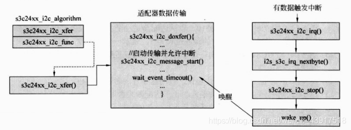
(2)中断处理函数s3c24xx_i2c_irq()
static irqreturn_t s3c24xx_i2c_irq(int irqno, void *dev_id)
{
	struct s3c24xx_i2c *i2c = dev_id;
	unsigned long status;  //IICSTAT状态缓存
	unsigned long tmp;    //寄存器的缓存

	status = readl(i2c->regs + S3C2410_IICSTAT);  //读IICSTAT的值

	if (status & S3C2410_IICSTAT_ARBITR) {  //因仲裁失败引发的中断
		/* deal with arbitration loss */
		dev_err(i2c->dev, "deal with arbitration loss\n");
	}

/*当总线为空闲状态时,由于非读写引起的中断,将执行下面的分支清除中断信号,继续传输数据*/
	if (i2c->state == STATE_IDLE) {
		dev_dbg(i2c->dev, "IRQ: error i2c->state == IDLE\n");

		tmp = readl(i2c->regs + S3C2410_IICCON);  //读IICCON寄存器
		tmp &= ~S3C2410_IICCON_IRQPEND;  /*将IICCON的位【4】清零,表示清除中断*/
		writel(tmp, i2c->regs +  S3C2410_IICCON);  //写IICCON寄存器
		goto out;  //跳到退出直接返回
	}

	/* pretty much this leaves us with the fact that we've
	 * transmitted or received whatever byte we last sent */

	i2s_s3c_irq_nextbyte(i2c, status);  //传输或者接收下一个字节

 out:
	return IRQ_HANDLED;
}
8.字节传输函数i2s_s3c_irq_nextbyte()
i2s_s3c_irq_nextbyte()函数用来传送下一个字节。
static int i2s_s3c_irq_nextbyte(struct s3c24xx_i2c *i2c, unsigned long iicstat)
{
	unsigned long tmp;
	unsigned char byte;
	int ret = 0;

	switch (i2c->state) {

	case STATE_IDLE:
		dev_err(i2c->dev, "%s: called in STATE_IDLE\n", __func__);
		goto out;
		break;

	case STATE_STOP:
		dev_err(i2c->dev, "%s: called in STATE_STOP\n", __func__);
		s3c24xx_i2c_disable_irq(i2c);
		goto out_ack;

	case STATE_START:
		/* last thing we did was send a start condition on the
		 * bus, or started a new i2c message
		 */

		if (iicstat & S3C2410_IICSTAT_LASTBIT &&
		    !(i2c->msg->flags & I2C_M_IGNORE_NAK)) {
			/* ack was not received... */

			dev_dbg(i2c->dev, "ack was not received\n");
			s3c24xx_i2c_stop(i2c, -ENXIO);
			goto out_ack;
		}

		if (i2c->msg->flags & I2C_M_RD)
			i2c->state = STATE_READ;
		else
			i2c->state = STATE_WRITE;

		/* terminate the transfer if there is nothing to do
		 * as this is used by the i2c probe to find devices. */

		if (is_lastmsg(i2c) && i2c->msg->len == 0) {
			s3c24xx_i2c_stop(i2c, 0);
			goto out_ack;
		}

		if (i2c->state == STATE_READ)
			goto prepare_read;

		/* fall through to the write state, as we will need to
		 * send a byte as well */

	case STATE_WRITE:
		/* we are writing data to the device... check for the
		 * end of the message, and if so, work out what to do
		 */

		if (!(i2c->msg->flags & I2C_M_IGNORE_NAK)) {
			if (iicstat & S3C2410_IICSTAT_LASTBIT) {
				dev_dbg(i2c->dev, "WRITE: No Ack\n");

				s3c24xx_i2c_stop(i2c, -ECONNREFUSED);
				goto out_ack;
			}
		}

 retry_write:

		if (!is_msgend(i2c)) {
			byte = i2c->msg->buf[i2c->msg_ptr++];
			writeb(byte, i2c->regs + S3C2410_IICDS);

			/* delay after writing the byte to allow the
			 * data setup time on the bus, as writing the
			 * data to the register causes the first bit
			 * to appear on SDA, and SCL will change as
			 * soon as the interrupt is acknowledged */

			ndelay(i2c->tx_setup);

		} else if (!is_lastmsg(i2c)) {
			/* we need to go to the next i2c message */

			dev_dbg(i2c->dev, "WRITE: Next Message\n");

			i2c->msg_ptr = 0;
			i2c->msg_idx++;
			i2c->msg++;

			/* check to see if we need to do another message */
			if (i2c->msg->flags & I2C_M_NOSTART) {

				if (i2c->msg->flags & I2C_M_RD) {
					/* cannot do this, the controller
					 * forces us to send a new START
					 * when we change direction */

					s3c24xx_i2c_stop(i2c, -EINVAL);
				}

				goto retry_write;
			} else {
				/* send the new start */
				s3c24xx_i2c_message_start(i2c, i2c->msg);
				i2c->state = STATE_START;
			}

		} else {
			/* send stop */

			s3c24xx_i2c_stop(i2c, 0);
		}
		break;

	case STATE_READ:
		/* we have a byte of data in the data register, do
		 * something with it, and then work out wether we are
		 * going to do any more read/write
		 */

		byte = readb(i2c->regs + S3C2410_IICDS);
		i2c->msg->buf[i2c->msg_ptr++] = byte;

 prepare_read:
		if (is_msglast(i2c)) {
			/* last byte of buffer */

			if (is_lastmsg(i2c))
				s3c24xx_i2c_disable_ack(i2c);

		} else if (is_msgend(i2c)) {
			/* ok, we've read the entire buffer, see if there
			 * is anything else we need to do */

			if (is_lastmsg(i2c)) {
				/* last message, send stop and complete */
				dev_dbg(i2c->dev, "READ: Send Stop\n");

				s3c24xx_i2c_stop(i2c, 0);
			} else {
				/* go to the next transfer */
				dev_dbg(i2c->dev, "READ: Next Transfer\n");

				i2c->msg_ptr = 0;
				i2c->msg_idx++;
				i2c->msg++;
			}
		}

		break;
	}

	/* acknowlegde the IRQ and get back on with the work */

 out_ack:
	tmp = readl(i2c->regs + S3C2410_IICCON);
	tmp &= ~S3C2410_IICCON_IRQPEND;
	writel(tmp, i2c->regs + S3C2410_IICCON);
 out:
	return ret;
}
9.适配器传输停止函数s3c24xx_i2c_stop()
s3c24xx_i2c_stop()函数主要完成个功能,如下所示:
(1)向总线发出结束P信号。
(2)唤醒等待在队列s3c24xx_i2c->wait中的进程,一次传输完毕。
(3)禁止中断,适配器中不产生中断信号。
static inline void s3c24xx_i2c_stop(struct s3c24xx_i2c *i2c, int ret)
{
	unsigned long iicstat = readl(i2c->regs + S3C2410_IICSTAT);
    //读IICSTAT寄存器

	dev_dbg(i2c->dev, "STOP\n");

	/* stop the transfer */
	iicstat &= ~S3C2410_IICSTAT_START;
   //写IICSTAT的位【5】为0,则发出P信号
	writel(iicstat, i2c->regs + S3C2410_IICSTAT);

	i2c->state = STATE_STOP;  //设置适配器为停止状态

	s3c24xx_i2c_master_complete(i2c, ret);  //唤醒传输等待队列中的进程
	s3c24xx_i2c_disable_irq(i2c);  //禁止中断
}
10.中断处理函数的一些辅助函数
i2s_s3c_irq_nextbyte()函数中使用了一些辅助函数,集中在这里介绍。这些函数如下所示:
(1)is_lastmsg()函数
static inline int is_lastmsg(struct s3c24xx_i2c *i2c)
{
	return i2c->msg_idx >= (i2c->msg_num - 1);
}
(2)is_msgend()函数
static inline int is_msgend(struct s3c24xx_i2c *i2c)
{
	return i2c->msg_ptr >= i2c->msg->len;
}
(3)禁止应答信号函数s3c24xx_i2c_disable_ack()
static inline void s3c24xx_i2c_disable_ack(struct s3c24xx_i2c *i2c)
{
	unsigned long tmp;

	tmp = readl(i2c->regs + S3C2410_IICCON);
   //IICCON的位【7】为0,表示不发出ACK信号
	writel(tmp & ~S3C2410_IICCON_ACKEN, i2c->regs + S3C2410_IICCON);
}
IIC设备层驱动程序
1.IC设备驱动模块加载和卸载
IIC设备驱动被作为一个单独的模块加入进内核,在模块的加载和卸载函数中需要注册和注销一个平台驱动结构体platform_driver。
(1)平台驱动的加载和卸载
加载:
static int __init i2c_adap_s3c_init(void)
{
	int ret;  //返回值

	ret = platform_driver_register(&s3c2410_i2c_driver);  //注册驱动程序
	if (ret == 0) {
		ret = platform_driver_register(&s3c2440_i2c_driver);  //再次注册
		if (ret)
			platform_driver_unregister(&s3c2410_i2c_driver);  //注销驱动程序
	}

	return ret;
}
卸载:
static void __exit i2c_adap_s3c_exit(void)
{
	platform_driver_unregister(&s3c2410_i2c_driver);  //注销平台驱动
	platform_driver_unregister(&s3c2440_i2c_driver);
}
(2)平台驱动s3c2410_i2c_driver
static struct platform_driver s3c2410_i2c_driver = {
	.probe		= s3c24xx_i2c_probe,
	.remove		= s3c24xx_i2c_remove,
	.suspend_late	= s3c24xx_i2c_suspend_late,
	.resume		= s3c24xx_i2c_resume,
	.driver		= {
		.owner	= THIS_MODULE,
		.name	= "s3c2410-i2c",
	},
};
2.探测函数s3c24xx_i2c_probe()
平台设备注册函数platform_driver_register()中会调用探测函数3c24xx_i2c_probe()。在该函数中将初始化适配器、IIC等硬件设备。其主要完成如下几个功能:
(1)申请一个适配器结构体i2c,并对其赋初值。
(2)获得i2c时钟资源。
(3)将适配器的寄存器资源映射到虚拟内存中。
(4)申请中断处理函数。
(5)初始化IIC控制器。
(6)添加适配器i2c到内核中。
static int s3c24xx_i2c_probe(struct platform_device *pdev)
{
	struct s3c24xx_i2c *i2c;
	struct s3c2410_platform_i2c *pdata;
	struct resource *res;
	int ret;

	pdata = pdev->dev.platform_data;
	if (!pdata) {
		dev_err(&pdev->dev, "no platform data\n");
		return -EINVAL;
	}

	i2c = kzalloc(sizeof(struct s3c24xx_i2c), GFP_KERNEL);
	if (!i2c) {
		dev_err(&pdev->dev, "no memory for state\n");
		return -ENOMEM;
	}

	strlcpy(i2c->adap.name, "s3c2410-i2c", sizeof(i2c->adap.name));
	i2c->adap.owner   = THIS_MODULE;
	i2c->adap.algo    = &s3c24xx_i2c_algorithm;
	i2c->adap.retries = 2;
	i2c->adap.class   = I2C_CLASS_HWMON | I2C_CLASS_SPD;
	i2c->tx_setup     = 50;

	spin_lock_init(&i2c->lock);
	init_waitqueue_head(&i2c->wait);

	/* find the clock and enable it */

	i2c->dev = &pdev->dev;
	i2c->clk = clk_get(&pdev->dev, "i2c");
	if (IS_ERR(i2c->clk)) {
		dev_err(&pdev->dev, "cannot get clock\n");
		ret = -ENOENT;
		goto err_noclk;
	}

	dev_dbg(&pdev->dev, "clock source %p\n", i2c->clk);

	clk_enable(i2c->clk);

	/* map the registers */

	res = platform_get_resource(pdev, IORESOURCE_MEM, 0);
	if (res == NULL) {
		dev_err(&pdev->dev, "cannot find IO resource\n");
		ret = -ENOENT;
		goto err_clk;
	}

	i2c->ioarea = request_mem_region(res->start, (res->end-res->start)+1,
					 pdev->name);

	if (i2c->ioarea == NULL) {
		dev_err(&pdev->dev, "cannot request IO\n");
		ret = -ENXIO;
		goto err_clk;
	}

	i2c->regs = ioremap(res->start, (res->end-res->start)+1);

	if (i2c->regs == NULL) {
		dev_err(&pdev->dev, "cannot map IO\n");
		ret = -ENXIO;
		goto err_ioarea;
	}

	dev_dbg(&pdev->dev, "registers %p (%p, %p)\n",
		i2c->regs, i2c->ioarea, res);

	/* setup info block for the i2c core */

	i2c->adap.algo_data = i2c;
	i2c->adap.dev.parent = &pdev->dev;

	/* initialise the i2c controller */

	ret = s3c24xx_i2c_init(i2c);
	if (ret != 0)
		goto err_iomap;

	/* find the IRQ for this unit (note, this relies on the init call to
	 * ensure no current IRQs pending
	 */

	i2c->irq = ret = platform_get_irq(pdev, 0);
	if (ret <= 0) {
		dev_err(&pdev->dev, "cannot find IRQ\n");
		goto err_iomap;
	}

	ret = request_irq(i2c->irq, s3c24xx_i2c_irq, IRQF_DISABLED,
			  dev_name(&pdev->dev), i2c);

	if (ret != 0) {
		dev_err(&pdev->dev, "cannot claim IRQ %d\n", i2c->irq);
		goto err_iomap;
	}

	ret = s3c24xx_i2c_register_cpufreq(i2c);
	if (ret < 0) {
		dev_err(&pdev->dev, "failed to register cpufreq notifier\n");
		goto err_irq;
	}

	/* Note, previous versions of the driver used i2c_add_adapter()
	 * to add the bus at any number. We now pass the bus number via
	 * the platform data, so if unset it will now default to always
	 * being bus 0.
	 */

	i2c->adap.nr = pdata->bus_num;

	ret = i2c_add_numbered_adapter(&i2c->adap);
	if (ret < 0) {
		dev_err(&pdev->dev, "failed to add bus to i2c core\n");
		goto err_cpufreq;
	}

	platform_set_drvdata(pdev, i2c);

	dev_info(&pdev->dev, "%s: S3C I2C adapter\n", dev_name(&i2c->adap.dev));
	return 0;

 err_cpufreq:
	s3c24xx_i2c_deregister_cpufreq(i2c);

 err_irq:
	free_irq(i2c->irq, i2c);

 err_iomap:
	iounmap(i2c->regs);

 err_ioarea:
	release_resource(i2c->ioarea);
	kfree(i2c->ioarea);

 err_clk:
	clk_disable(i2c->clk);
	clk_put(i2c->clk);

 err_noclk:
	kfree(i2c);
	return ret;
}
3.移除函数s3c24xx_i2c_remove()
与s3c24xx_i2c_probe()函数完成相反功能的函数是s3c24xx_i2c_remove()函数,它在模块卸载函数调用platform_driver_unregister()函数时通过platform_driver的remove指针被调用。
static int s3c24xx_i2c_remove(struct platform_device *pdev)
{
	struct s3c24xx_i2c *i2c = platform_get_drvdata(pdev);

	s3c24xx_i2c_deregister_cpufreq(i2c);

	i2c_del_adapter(&i2c->adap);
	free_irq(i2c->irq, i2c);

	clk_disable(i2c->clk);
	clk_put(i2c->clk);

	iounmap(i2c->regs);

	release_resource(i2c->ioarea);
	kfree(i2c->ioarea);
	kfree(i2c);

	return 0;
}
4.控制器初始化函数s3c24xx_i2c_init()
探测函数s3c24xx_i2c_probe()中调用s3c24xx_i2c_init()函数来初始化乎适配器。
static int s3c24xx_i2c_init(struct s3c24xx_i2c *i2c)
{
	unsigned long iicon = S3C2410_IICCON_IRQEN | S3C2410_IICCON_ACKEN;
	struct s3c2410_platform_i2c *pdata;
	unsigned int freq;

	/* get the plafrom data */

	pdata = i2c->dev->platform_data;

	/* inititalise the gpio */

	if (pdata->cfg_gpio)
		pdata->cfg_gpio(to_platform_device(i2c->dev));

	/* write slave address */

	writeb(pdata->slave_addr, i2c->regs + S3C2410_IICADD);

	dev_info(i2c->dev, "slave address 0x%02x\n", pdata->slave_addr);

	writel(iicon, i2c->regs + S3C2410_IICCON);

	/* we need to work out the divisors for the clock... */

	if (s3c24xx_i2c_clockrate(i2c, &freq) != 0) {
		writel(0, i2c->regs + S3C2410_IICCON);
		dev_err(i2c->dev, "cannot meet bus frequency required\n");
		return -EINVAL;
	}

	/* todo - check that the i2c lines aren't being dragged anywhere */

	dev_info(i2c->dev, "bus frequency set to %d KHz\n", freq);
	dev_dbg(i2c->dev, "S3C2410_IICCON=0x%02lx\n", iicon);

	/* check for s3c2440 i2c controller  */

	if (s3c24xx_i2c_is2440(i2c)) {
		dev_dbg(i2c->dev, "S3C2440_IICLC=%08x\n", pdata->sda_delay);

		writel(pdata->sda_delay, i2c->regs + S3C2440_IICLC);
	}

	return 0;
}
5.设置控制器数据发送频率函数s3c24xx_i2c_clockrate()
控制器初始化函数s3c24xx_i2c_init()中调用了s3c24xx_i2c_clockrate()函数来设置数据发送频率。此发送频率由IICCON寄存器来控制。发送频率可以由一个公式得到,这个公式是: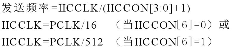
static int s3c24xx_i2c_clockrate(struct s3c24xx_i2c *i2c, unsigned int *got)
{
	struct s3c2410_platform_i2c *pdata = i2c->dev->platform_data;
	unsigned long clkin = clk_get_rate(i2c->clk);
	unsigned int divs, div1;
	u32 iiccon;
	int freq;
	int start, end;

	i2c->clkrate = clkin;
	clkin /= 1000;		/* clkin now in KHz */

	dev_dbg(i2c->dev, "pdata %p, freq %lu %lu..%lu\n",
		 pdata, pdata->bus_freq, pdata->min_freq, pdata->max_freq);

	if (pdata->bus_freq != 0) {
		freq = s3c24xx_i2c_calcdivisor(clkin, pdata->bus_freq/1000,
					       &div1, &divs);
		if (freq_acceptable(freq, pdata->bus_freq/1000))
			goto found;
	}

	/* ok, we may have to search for something suitable... */

	start = (pdata->max_freq == 0) ? pdata->bus_freq : pdata->max_freq;
	end = pdata->min_freq;

	start /= 1000;
	end /= 1000;

	/* search loop... */

	for (; start > end; start--) {
		freq = s3c24xx_i2c_calcdivisor(clkin, start, &div1, &divs);
		if (freq_acceptable(freq, start))
			goto found;
	}

	/* cannot find frequency spec */

	return -EINVAL;

 found:
	*got = freq;

	iiccon = readl(i2c->regs + S3C2410_IICCON);
	iiccon &= ~(S3C2410_IICCON_SCALEMASK | S3C2410_IICCON_TXDIV_512);
	iiccon |= (divs-1);

	if (div1 == 512)
		iiccon |= S3C2410_IICCON_TXDIV_512;

	writel(iiccon, i2c->regs + S3C2410_IICCON);

	return 0;
}
更多推荐

 2
2 0
0- 0


 已为社区贡献1条内容

所有评论(0)